Engineering selection / Tooling & stamping

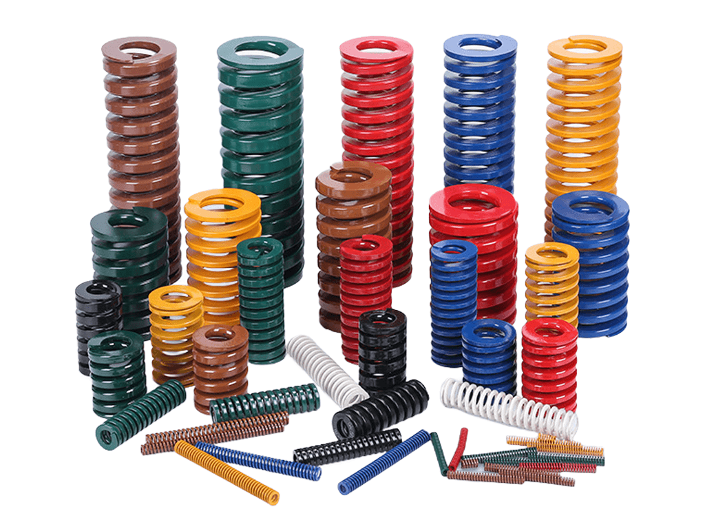
Die springs for tooling and stamping

Select springs for stripper plates, pressure pads and return mechanisms. Start with the installed length, actual spring travel and required loads at two working positions. Then check the JIS, ISO or US series, or request a spring made to your drawing or sample.

Dingli JIS die springs
Dingli die springs · Check dimensions and loads for the selected model

01 / Operating Condition Identification

Start with the applicationThen define the checks

First, describe the action the spring performs in the mechanism. The force stages for stripping, pressure holding, and returning differ; replacements for existing tools also require preserving the original assembly conditions.

Stripper plate · Verify the stripping force

Stripper plate: Correlate the stripping force with the actual spring compression

The spring compresses during die closing and pushes the stripper plate during die opening. Verify the spring length and load at the start and end of stripping to ensure sufficient force is available during the required stages.

Information to provide
  • The actual travel of the stripper plate, the spring assembly height, and the shortest working length; clarify whether the mechanism directly compresses the spring.
  • The working position requiring stripping force, the total stripping force requirement, the number of springs, and their layout positions; indicate whether the values are per spring or for the entire group.
  • Stamping frequency, operating time per shift, as well as structural drawings of the bore, guide rod, and spring seat.
Selection checks
  • The sum of assembly precompression and working stroke remains within the applicable working range of the selected model.
  • The load at each force point meets the stripping requirements; check for balanced load distribution in conjunction with the layout.
  • Guide and end-face support match; the mechanism stop does not subject the spring to additional compression.

Commonly overlooked: Assuming the press slide stroke is the spring stroke, or only verifying the maximum force at die closure while neglecting the force during the die opening/stripping stage.

If documentation is incomplete: Provide partial tool drawings, spring installation photos, and the stripper plate travel first; mark load as "to be confirmed" if unknown, and retain the original model number or sample information.

Pressure pad · Verify both contact and closed positions

Pressure pad: Confirm the initial force upon contact and the working force at die closure

The spring force differs when the pressure pad first contacts the workpiece and during subsequent compression. Describe the workpiece, pressure points, and the allowable force range, then verify the load variation in conjunction with the actual pressing process.

Information to provide
  • The spring length when the pressure pad contacts the workpiece, the shortest length at die closure, and the actual compression between these two positions.
  • The total pressure force required during the contact stage, the allowable load range during die closure, the number of springs, and the pressure pad layout diagram.
  • The workpiece material, thickness, and surface requirements; state if there are marks, wrinkles, or localized force anomalies, and provide physical photos.
Selection checks
  • The load corresponding to both lengths meets the design requirements; do not only confirm the endpoint load.
  • Check for balanced load distribution in conjunction with spring layout, pressure pad support, and guidance; confirm the mechanism's own load-bearing conditions.
  • Sum the precompression and additional working stroke, then verify the model's working range and actual stamping frequency.

Commonly overlooked: Describing the modification goal as "stiffer" without specifying the initial force upon contact; or neglecting that increasing precompression will also change the closed die load and total compression.

If documentation is incomplete: First send a partial pressure pad drawing, workpiece condition, and the phenomenon you wish to improve; if force values are unavailable, provide the original model, assembly height, and closed die length as a starting point for verification.

Return Mechanism · Verify the force at the return endpoint

Return Mechanism: Check the force at the return endpoint, and also verify the compression endpoint

The spring pushes the mechanism back to the target position as it releases compression. Selection requires verifying that the compression endpoint is within the working range and that the force near the end of return can meet the mechanism's needs.

Information to provide
  • The mechanism action diagram, return start and end points, spring assembly length, and actual travel; clarify if force is transmitted via lever or cam.
  • The gravity, friction, or other resistance to be overcome during the return process, and the force requirement at the target position.
  • The spring installation direction, end support, guide rod or spring bore dimensions, as well as action frequency and temperature.
Selection checks
  • The load at the return endpoint meets the design needs; if it fails to reach position, also check for binding, friction, and mechanism resistance.
  • The total compression at the compression endpoint is within the model's working range; the mechanism stop is compatible with the spring stroke.
  • Transmission ratio, support, and guidance conditions have been incorporated into the verification; for long springs or horizontal installation, provide complete structural information.

Commonly overlooked: Selecting based solely on the maximum load at the shortest working position, neglecting the load decrease at the return endpoint; or directly equating the mechanism's travel with the spring compression.

If documentation is incomplete: First provide a video of the action or a schematic diagram of the mechanism, photos of the original spring, and a description of the position where it fails to reach, then supplement with assembly length, travel, and force requirements.

Existing tool replacement · Keep the original specification and conditions

Existing tool replacement: recover the specification and check for changed conditions

First, distinguish between periodic replacement, failure replacement, and performance modification. That the original spring fits does not mean that merely copying dimensions will restore the original load and working range; tool regrinding, stroke adjustments, and changes in operating frequency should also be noted.

Information to provide
  • The original manufacturer, model, standard series, color, and catalog records; provide an intact sample or measured dimensions of the old part indicating its condition.
  • The spring bore, guide rod, assembly length, shortest working length, and number in the same group; retain the original drawing version.
  • The reason for replacement, operating time or cycles, and photos of the failure location; state any recent tool regrinding, changes in operating conditions, or medium.
Selection checks
  • Whether the loads at the same length, allowable total compression, and installation fit of the new and old models match.
  • Whether the length or outer diameter of the old sample has changed due to deformation and wear; do not directly treat these changes as design dimensions.
  • The consistency of specifications and loads within the same force group, and whether guidance or assembly conditions need adjustment along with the replacement.

Commonly overlooked: Assuming interchangeability based solely on color and appearance, or directly increasing the load rating upon encountering breakage without first checking total compression and guidance.

If documentation is incomplete: First send the original model, photos of the old part and installation, quantity, and reason for replacement; if the original model is missing, supplement with inner/outer diameter, unloaded length, and note whether the sample is intact.

02 / Length and Load

Separate precompression and travelCheck total compression

A spring may already be compressed when installed in the tool. The working stroke generated by continued mechanism movement must be added to this precompression. When verifying the catalog's allowable compression, do not compare only the mechanism stroke.

Dimensional Relationship Example · Not a Model Recommendation

Free State L₀

50 mm

Length of the spring when unloaded, used to define the starting point for compression.

Assembly State L₁

45 mm

Assembly precompression is 50 − 45 = 5 mm; assembly load is already present at this state.

Shortest Working State L₂

35 mm

Further compression of 10 mm; total compression relative to free length is 15 mm.

This example should be checked against the model using a total compression of 15 mm.

It only illustrates the length relationship and does not indicate that a particular spring model allows for 15 mm of compression. Allowable working compression, cycle conditions, and solid height must still be verified for the corresponding model. Solid height is the length at which the coils touch and cannot be used as the normal working endpoint.

Assembly Load F₁
Expressed as "When the spring length is L₁ mm, the required load per spring is F₁ N", used to confirm the force at the mechanism's initial position.
Working Load F₂
Expressed as "When the spring length is L₂ mm, the required load per spring is F₂ N", then verify other working positions requiring force.
Spring Rate k
Unit is typically N/mm. Within the linear working range, the rate can be used to estimate load changes between different compressions; finally confirm according to the model's load table or agreed test points.
Total Group Force
Note the total requirement, number of springs, and layout. Only when the spring specifications, compression, and force conditions are identical can the total group force be estimated by summing individual spring loads.

03 / Engineering Selection

Follow six stepsBuild a verifiable specification

First confirm the dimensions fit within the space, then confirm the force and compression over the entire stroke. Color and load grade can be used to identify series, but specific models still require item-by-item verification.

  1. Sketch the actual installation space for the spring

    Record the spring hole diameter, hole depth, guide rod diameter, assembled height, and end face structure. Distinguish between "spring measured outer/inner diameter" and "fitting hole/rod diameter"; the nominal installation dimensions in the catalog may not equal the actual spring size, and clearance must be confirmed according to the specific model requirements.

  2. Mark the start and end points on the assembly drawing

    Mark the free length, assembled length, and minimum working length, and calculate the precompression and total compression separately. If the mechanism has levers, cams, or other drive structures, provide the actual movement at the spring location; do not directly apply the total stroke of the equipment.

  3. Specify the required force at each position

    At minimum, specify the load requirements at the assembled position and the minimum working position. Use units such as N, kgf, or lbf, and distinguish between single-unit load and load for the entire set; simply writing "heavy load" or "needs to be harder" is insufficient to confirm specifications.

  4. Filter allowable compression range using operating frequency

    Provide cycles per minute, daily operating time, maintenance intervals, and target service life requirements. The applicable range for the same model may differ under varying compression and cycling conditions; do not treat the limit values in the catalog as long-term working values for all conditions.

  5. Check guidance, support, and mechanism limits

    Confirm the fit between the guide rod or spring hole, guide length, support end face and parallelism, and check whether metal chips might enter the coils. Also verify the mechanism's minimum position and possible overtravel to keep the spring's actual operating range within the confirmed limits.

  6. Write sample approval and batch acceptance conditions into the specification

    Confirm drawing version, dimensional tolerances, load and tolerance at specified length, material, and surface requirements. When lifespan or environmental verification is needed, agree on precompression, stroke, frequency, temperature, and acceptance criteria together to facilitate consistent standards for samples and subsequent batches.

04 / Standards & Replacement

JIS, ISO and USIdentify the series first

Dingli die springs cover JIS, ISO, and US series. For replacements, retain the original model and catalog information, and compare dimensions, load capacity, and allowable compression in the same units.

JIS

When the drawing or original catalog specifies a JIS series

  • Confirm the original model and series designation.
  • Verify installation dimensions, free length, and load class.
  • Then confirm working load based on actual total compression.
ISO

When the drawing or equipment specifies an ISO series

  • Retain the standard requirements and original manufacturer model.
  • Cross-check the hole diameter, rod diameter, and length definitions in the catalog.
  • Compare the load and working range under the same compression.
US

When the original equipment uses a US standard series

  • Retain the original inch or metric specifications.
  • Also note the load units and original series.
  • Check item by item after conversion; do not select based solely on similar dimensions.

Color alone cannot be used as the basis for cross-series replacement.

The correspondence between color and load class may differ across series or manufacturers. Even if the color, outer diameter, and free length are identical, you should continue to compare the load at the specified length, allowable compression, guide fit, and end conditions.

Start from Standard Models

When standard requirements or an original model exist, and dimensions, working load, stroke, and environment can be covered by a catalog model, first verify the standard series. Before ordering, record the complete model, quantity, and operating conditions.

Proceed to Custom Manufacturing Review Based on Drawing or Sample

When a standard model cannot simultaneously meet space, stroke, load, or material requirements, submit the assembly drawing and load points; if only a sample is available, also explain the actual application and existing issues to avoid merely replicating dimensions that are already worn or deformed.

05 / Troubleshooting

Replacing an existing springRecord the symptoms first

The following are the key clues to verify during communication. Breakage, length changes, and unstable action can be caused by multiple conditions simultaneously and cannot be determined solely from a single photo.

Repeated breakage or significantly shortened replacement cycle

First, record: The breakage location, runtime or cycle count, condition of other springs in the same group, and whether the die has been ground, the stroke adjusted, or the stamping frequency increased recently.

Then verify: The total compression including precompression, operating range, guide friction, mounting end faces, and presence of foreign objects. Provide close-up photos of the fracture and wear areas, combined with actual operating conditions, to confirm if specification adjustments or assembly conditions are needed.

Insufficient stripping, incomplete return, or unstable action

First, record: At which work position the problem occurs, whether it is consistent between cold start and continuous operation, and whether there is jamming or friction change.

Then verify: The spring length and load at that position, assembly precompression, number of springs and force distribution, and check the mechanism resistance. Before selecting a higher load grade, also review the total compression and structural load-bearing conditions.

Spring shortening, tilting, or surface abrasion marks

First, record: The free length after unloading, the difference from a new part or the original drawing, and the distribution of the abrasion marks; retain a non-failed sample from the same group for comparison.

Then verify: Whether the operating range is exceeded, whether the end faces are misaligned, or whether the bore or guide rod is interfering. Do not alter die spring specifications by shortening coils or grinding inner/outer diameters; re-check the appropriate model or custom requirements instead.

Rust, coating peeling, or condition change after cleaning

First, record: The name, concentration, temperature, and duration of the liquid contact, and whether it has been rinsed, dried, or stored in a damp environment.

Then verify: Whether the base material and surface finish match the contact environment, and also check for mechanical scratches. When ordering replacements, specify the environmental conditions and appearance requirements; protective performance cannot be judged solely by coating color.

Replacements within the same load group should verify overall consistency. If new and old parts or different specifications are mixed, it is necessary to evaluate the force and load distribution of each spring at the same assembly length.

06 / Materials & Environment

Materials and finishesMatch the environment

Material grades, heat treatment, and surface finish serve different roles. First, specify the operating temperature, contact media, and cycling conditions, then verify the material selection; the specific materials for standard series are subject to the corresponding specification, and special material requirements are evaluated based on drawings.

Checks for indoor, wet, hot and frequent-cycle conditions
Ambient Indoor Conditions
State whether contact with stamping oil, coolant, or metal debris is involved, as well as cleaning and maintenance methods. Verify material and surface finish requirements in conjunction with load and cycling conditions.
Humid or Washdown Environments
Provide the media name, concentration, contact method, and duration. If salt spray or corrosion testing is required, specify the test conditions and acceptance criteria, then evaluate the base material and protective solution.
Sustained High-Temperature Conditions
Differentiate between the ambient temperature and the spring's actual operating temperature. Specify the duration, peak value, and thermal cycling. Material temperature data needs to be understood in conjunction with load, time, and performance retention requirements.
High-Frequency Cycling Conditions
Provide the precompression, stroke, frequency, and target maintenance interval. Comprehensively verify the stress and fatigue conditions. Changing the material cannot replace the investigation of over-compression, off-center loading, or guidance issues.

07 / Sample & Acceptance

Confirm the sampleDefine repeat-order criteria

After the selection discussion, a verifiable specification record should be kept. Separate agreements on dimensions, load, and trial requirements facilitate that procurement, engineering, and both supply parties use the same documentation.

Acceptance records: dimensions, loads, materials and trials
Dimensions & Installation
Drawing number and version, complete model, key dimensions and tolerances, mating holes and guide rods, end requirements; record interference or misalignment during assembly verification.
Load Testing
Test length, corresponding load and tolerance, testing unit and conditions. Specify multiple load points individually; avoid stating only "stiffness qualified" without the assembly force basis.
Material & Surface
Material grade, surface finish, appearance, and protection requirements. List and confirm the applicability of material certificates, inspection reports, or other documents during the inquiry stage.
Trial & Reorder
Record actual precompression, stroke, frequency, temperature, and anomalies; agree on trial acceptance criteria; bring confirmed drawings, sample records, and version information for reorders.

08 / Procurement FAQ

Before your inquirySix purchasing questions

Can we start communication with only an old spring and photos?

Please provide photos showing the side, end, markings, and mounting location first, and record the free length and inner/outer diameters. If the old part is broken, worn, or deformed, indicate the condition of the measured object. The original model, original drawing, or intact sample from the same set is more conducive to restoring the specifications.

If the load is unknown, can we purchase based solely on dimensions?

Dimensions can be used for screening but are insufficient to confirm performance. First provide the original model or sample, assembled length, actual travel, and application. Clarify which load parameters remain to be confirmed, then supplement with design requirements or agree on a sample verification method.

Can springs with the same color and dimensions be directly interchanged?

You need to further verify the original series and specific model, and compare the load, allowable compression, and mounting fit at the same length. Color identification relies on the corresponding catalog; cross-standard or cross-manufacturer replacement cannot be judged solely by appearance.

The travel is already determined, why is the assembled height still required?

Because the assembled height determines the precompression. The same working travel will result in different total compression and force ranges under different assembly precompressions, and will also affect the verification of the model's working range.

Can a uniform service life be provided directly?

Service life is related to the model, precompression, working travel, frequency, temperature, guidance, and environment. When a life assessment or verification is required, these conditions and failure criteria should be clearly stated first. A single general cycle count cannot represent all installation conditions.

What purchasing requirements need to be specified before requesting a quotation?

Specify the model or drawing, sample and batch quantity, delivery location, target lead time, as well as packaging, labeling, and inspection document requirements. The lead time, minimum order quantity, and inspection scope are confirmed based on specific specifications and the order.

09 / Inquiry Information

Drawing or old springStart with what you have

Dingli Spring supports standard die spring and custom manufacturing based on drawings or samples. Please send us the application, existing model or photos, installation dimensions, and quantity first; mark uncertain items as "to be confirmed," and we will verify them step-by-step based on operating conditions.

Prepare your inquiry

Use these eight items to prepare one inquiry for engineering and purchasing.

  • Application & Situation: Stripping/pressing/returning; new tool, replacement part, or modification; specific problems to solve.
  • Model or Drawing: Standard series, original manufacturer & model, drawing number & version; provide samples and installation photos if no drawings available.
  • Installation Space: Measured inner/outer diameter, free length, bore diameter, bore depth, guide rod diameter, and assembled length; specify mm or inch.
  • Stroke & Load: precompression, actual stroke, minimum working length; load and tolerance at specified length, state units, per piece/set, and quantity.
  • Cycle & Environment: Frequency, operating time, maintenance cycle; normal and peak temperatures, contact media, and cleaning method.
  • Material & Inspection: Specified material, surface finish, dimensional and load inspection requirements, required documentation.
  • Quantity & Delivery: Sample and batch quantity, repeat order needs, target lead time, location, and packaging/labeling requirements.
  • Missing Info & Supplements: Mark parameters to be confirmed; for replacements, add failure photos and original operating records.

With photos only: First add dimensions and installation location. With sample: State if it is intact and its original operating conditions. With drawing: Include version and load points. In all three cases, specify quantity and target lead time.

Inquiry Email: jackchen@dinglispring.com

WhatsApp: +86 13586942004

Panoramic view of the Dingli Spring factory

Send your dataand files to Dingli

Start with a drawing, an existing part number or photos of the old spring. Include quantities, target delivery and any parameters still to be confirmed.

Email your files